 Welding with
 low distortion
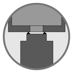
The weld geometry at CD-welding is usually
carried out with one projection diameter, or some single projections.
Two work pieces are pressed together hydraulically, pneumatically, hydropneumatically or by means of a servo motor with a low pre force. At this point the part height is measured by an integrated way measuring system. After that the welding force is applied.
Generally the pressure unit transfers the force on polymer or steel springs which transmit the force to the upper electrode and further to the work pieces. Once the weld force is reached, the electric energy is discharged from the capacitors through transformers and generates a Joule heating at the contact of the weld projection. A sufficiently high diffusion temperature is reached and the joining of the parts is initiated.
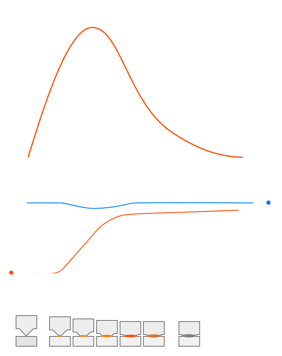
As shown schematically in the picture, the actual welding occurs between the times tth and th. The maximum Joule heating is reached during the maximum welding current I p at the time t p. Thereafter, the generated heat in the weld projections is less than the self-quenching in the surrounding material. The joining zone solidifies and the parts are welded together. One important point to consider at CD-welding is that the system technology allows fast repositioning of the electrodes. Otherwise there could be to insufficient welding.
One important point to consider at CD-welding is that the system technology allows fast repositioning of the electrodes. Otherwise there could be to insufficient welding.
Multiple discharges
for hardness reduction
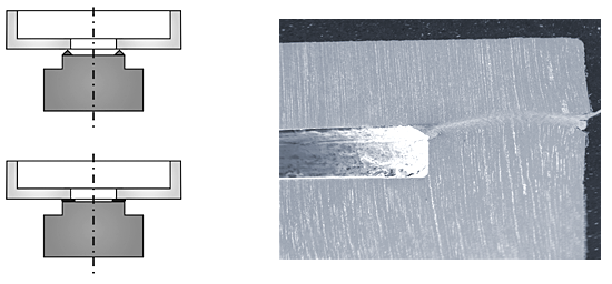
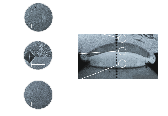
The following drawing shows two work pieces before and after welding. The metallographic picture shows a welded projection with a very narrow weld zone.
CD-welding has the advantage of an additional energy discharge in the already welded part. This leads to a local heating of the weld zone which is equal to annealing followed by a hardness reduction.
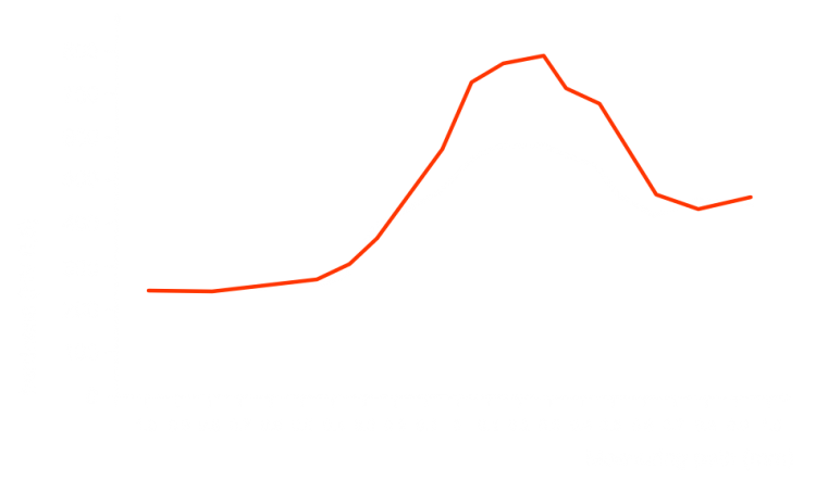
If high carbon steel is welded, it comes to a rapid self-quenching followed by a high hardness in the weld zone. This can result in cracking in the weld zone. In addition, there is a very brittle material behavior under static and dynamic loading of the weld. The following picture shows how the hardness of about 800 HV 0.5 is reduced to about 600 HV 0.5 by a second annealing discharge. The energy of one or multiple discharges can also be adjusted to the parts or the material used.
